Difference between revisions of "Test"
From 100ybp
| Line 6: | Line 6: | ||
</head> | </head> | ||
<style> | <style> | ||
| + | body {font-family: "source sans pro";} | ||
h2 {font-style: "semi-bold"; text-align: "center";} | h2 {font-style: "semi-bold"; text-align: "center";} | ||
div#presentation {width: 100%;} | div#presentation {width: 100%;} | ||
| Line 12: | Line 13: | ||
</style> | </style> | ||
<body> | <body> | ||
| − | + | <div id="presentation"> | |
<div > | <div > | ||
<video muted preload="auto" autoplay loop width="850"> | <video muted preload="auto" autoplay loop width="850"> | ||
| Line 21: | Line 22: | ||
<div style="height:30px; width: 850px; margin:0px; padding: 0px; padding-top: 20px; border: 0px;"> | <div style="height:30px; width: 850px; margin:0px; padding: 0px; padding-top: 20px; border: 0px;"> | ||
<div style="float:left; width: 158px; height 30px; border: 1px solid #aaa; margin-right:10px; margin-bottom:10px;" align="center"> | <div style="float:left; width: 158px; height 30px; border: 1px solid #aaa; margin-right:10px; margin-bottom:10px;" align="center"> | ||
| − | <p>< | + | <p><a href="/index.php/project09:Main" title="project09:Main"><b>Main</b></a> |
</p> | </p> | ||
</div> | </div> | ||
| Line 33: | Line 34: | ||
</div> | </div> | ||
<div style="float:left; width: 158px; height 30px; border: 1px solid #aaa; margin-right:10px; margin-bottom:10px;" align="center"> | <div style="float:left; width: 158px; height 30px; border: 1px solid #aaa; margin-right:10px; margin-bottom:10px;" align="center"> | ||
| − | <p>< | + | <p><strong><b>Prototyping</b></strong> |
</p> | </p> | ||
</div> | </div> | ||
<div style="float:left; width: 158px; height 30px; border: 1px solid #aaa; margin-right:10px; margin-bottom:10px;" align="center"> | <div style="float:left; width: 158px; height 30px; border: 1px solid #aaa; margin-right:10px; margin-bottom:10px;" align="center"> | ||
| − | <p><a href="/index.php/project09:Final_Presentation" title="project09:Final_Presentation"><b>Final Presentation</b></a> | + | <p><a href="/index.php/project09:Final_Presentation" title="project09:Final_Presentation"><b>Final Presentation</b></a> |
</p> | </p> | ||
</div> | </div> | ||
| + | </div> | ||
| + | |||
| + | <h2>Node</h2> | ||
| + | <br> | ||
| + | |||
| + | <iframe src="https://onedrive.live.com/embed?cid=40A9C0850F2A879D&resid=40A9C0850F2A879D%21199695&authkey=AJhRQyzenFy_Qvs&em=2" width="850" height="691" frameborder="0" scrolling="no"></iframe> | ||
| + | |||
| + | |||
| + | <br> | ||
| + | <br> | ||
| + | |||
| + | In a workshop which I did with Erik Bakker in the robotic building studio we developed a design process for a steel 3D-printed structural node. The aim was to develop a generic design process applicable to different structural situations in which a node is created by means of topological optimization. In order to develop the process we used a situation from Erik’s design during the workshop, to later apply it in my own project. The elaboration of the node in my project is further explained here. | ||
| + | <br> | ||
| + | <br> | ||
| + | In the situation two beams cross each other, which need to be structurally connected. This will be done by the node that is to be designed, which will be attached to the beams by the use of bolts. The positions of these bolts are used as loads and supports in a topological optimization process. The process is subdivided in eight different conditions: normal forces, shear forces, moment forces and orthogonal forces, for both beams respectively, with the other beam’s bolts acting as supports. This is done to ensure all forces are covered by the node. The forces are received from structural analysis of the whole construction. | ||
| + | <br> | ||
| + | <br> | ||
| + | In the situation a bounding volume is appointed in which the node may emerge. From this volume voids are cut for reasons of assembly and neighboring beams. With the use of a plug-in for grasshopper in Rhino called tOpos, the volume is divided in voxels which are iteratively removed according to structural relevance. Subsequently, the resulting voxels are collected and wrapped in geometry. This geometry is then fine-tuned and the holes for the bolts are ensured. | ||
| + | <br> | ||
| + | <br> | ||
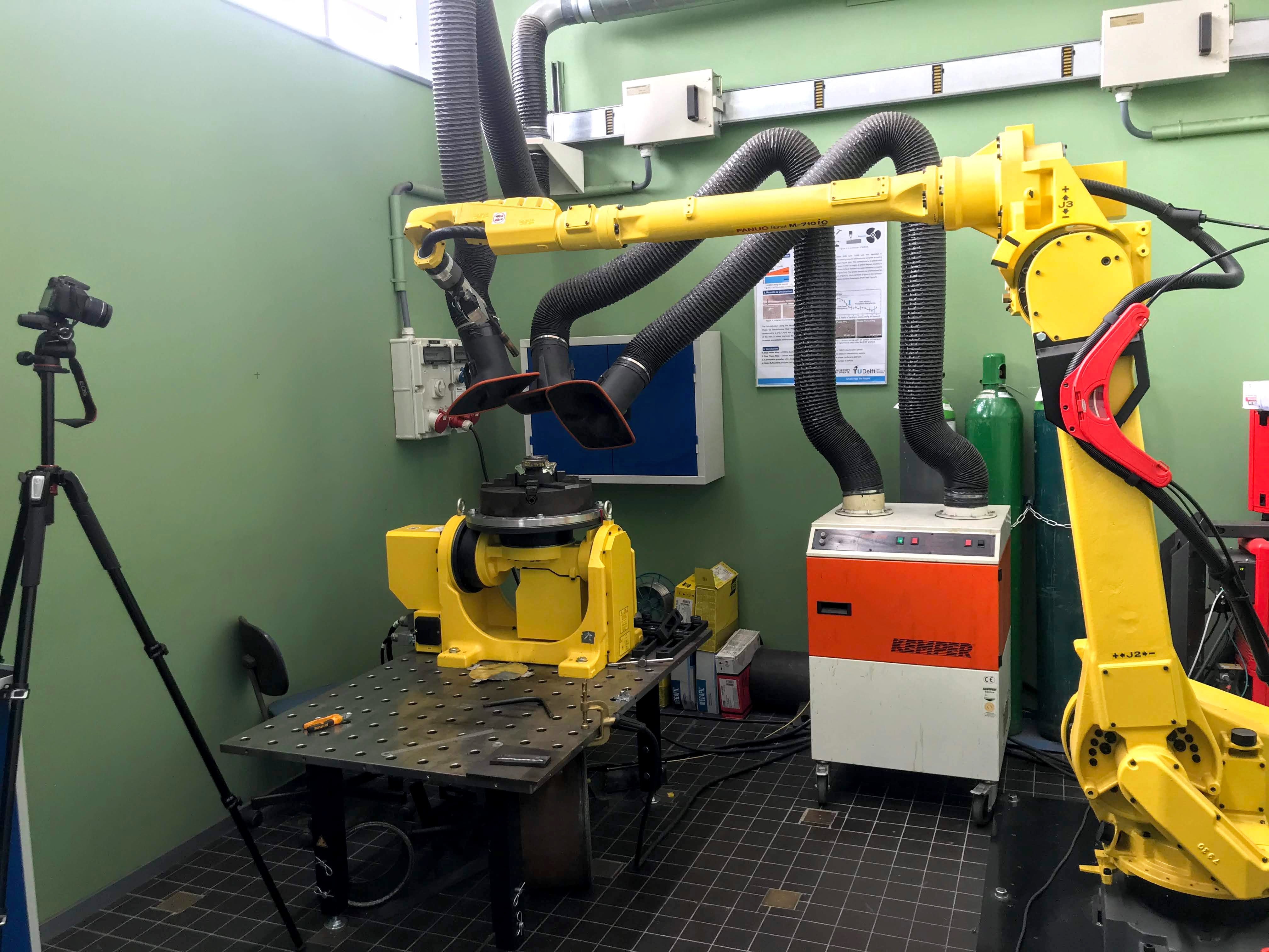
| + | In current developments we are looking to prototype the geometry 1:1 by means of WAAM printing. A strategy has been developed for the generation of toolpaths and the first tests are ready to be printed. Updates will follow here. | ||
| + | <br> | ||
| + | <br> | ||
| + | |||
| + | <h2>Robotic Setup</h2> | ||
| + | <br> | ||
| + | <img src="http://100ybp.roboticbuilding.eu/images/5/5e/Setup.jpg"> | ||
| + | <br> | ||
| + | <br> | ||
| + | |||
| + | |||
| + | <h2>Dry Run</h2> | ||
| + | <br> | ||
| + | <video preload="none" controls> | ||
| + | <source src="https://onedrive.live.com/download?cid=40A9C0850F2A879D&resid=40A9C0850F2A879D%21243684&authkey=ABm6CdLAUEjNcLw" type="video/mp4"> | ||
| + | </video> | ||
| + | <br> | ||
| + | <br> | ||
| + | |||
| + | |||
| + | <h2>Printing Layer</h2> | ||
| + | <br> | ||
| + | <video preload="none" controls> | ||
| + | <source src="https://onedrive.live.com/download?cid=40A9C0850F2A879D&resid=40A9C0850F2A879D%21243713&authkey=AHWqivfuRy3XaH4" type="video/mp4"> | ||
| + | </video> | ||
| + | <br> | ||
| + | <br> | ||
| + | |||
| + | <h2>Filtered Footage</h2> | ||
| + | <br> | ||
| + | <video preload="none" controls> | ||
| + | <source src="https://onedrive.live.com/download?cid=40A9C0850F2A879D&resid=40A9C0850F2A879D%21243712&authkey=ABxTeNFlULHSBa8" type="video/mp4"> | ||
| + | </video> | ||
| + | <br> | ||
| + | |||
| + | </div> | ||
| + | </body> | ||
| + | </html> | ||
Revision as of 16:34, 16 June 2020
Node
In a workshop which I did with Erik Bakker in the robotic building studio we developed a design process for a steel 3D-printed structural node. The aim was to develop a generic design process applicable to different structural situations in which a node is created by means of topological optimization. In order to develop the process we used a situation from Erik’s design during the workshop, to later apply it in my own project. The elaboration of the node in my project is further explained here.
In the situation two beams cross each other, which need to be structurally connected. This will be done by the node that is to be designed, which will be attached to the beams by the use of bolts. The positions of these bolts are used as loads and supports in a topological optimization process. The process is subdivided in eight different conditions: normal forces, shear forces, moment forces and orthogonal forces, for both beams respectively, with the other beam’s bolts acting as supports. This is done to ensure all forces are covered by the node. The forces are received from structural analysis of the whole construction.
In the situation a bounding volume is appointed in which the node may emerge. From this volume voids are cut for reasons of assembly and neighboring beams. With the use of a plug-in for grasshopper in Rhino called tOpos, the volume is divided in voxels which are iteratively removed according to structural relevance. Subsequently, the resulting voxels are collected and wrapped in geometry. This geometry is then fine-tuned and the holes for the bolts are ensured.
In current developments we are looking to prototype the geometry 1:1 by means of WAAM printing. A strategy has been developed for the generation of toolpaths and the first tests are ready to be printed. Updates will follow here.
Robotic Setup